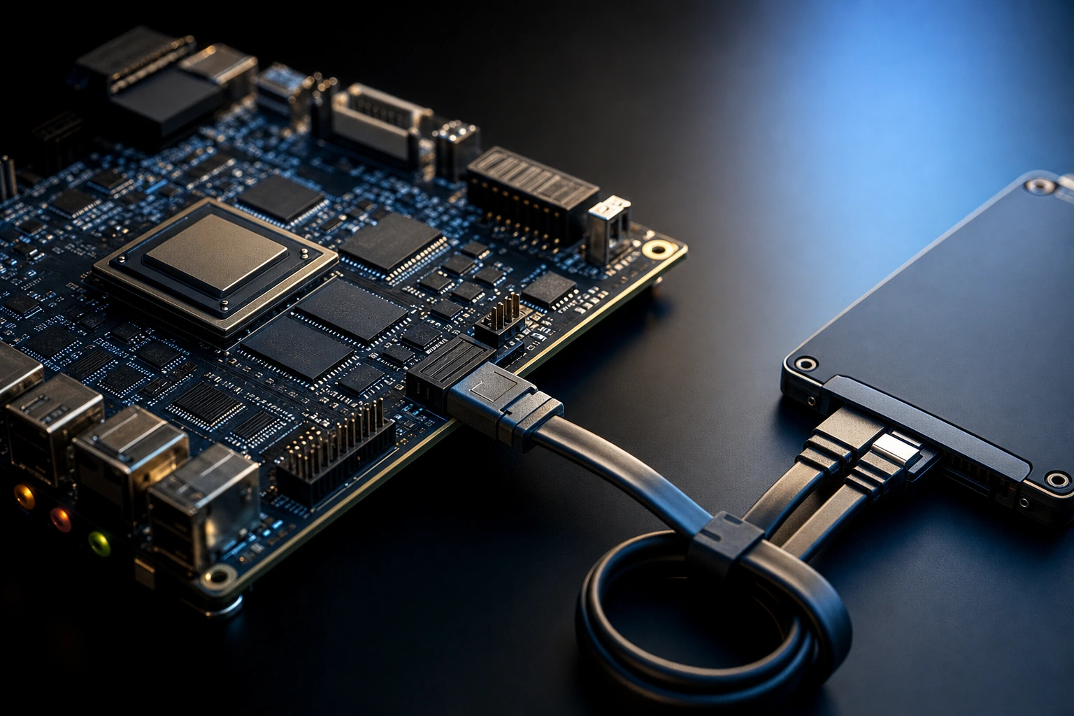
Industry update — In January 2026, Microchip expanded its PolarFire FPGA video ecosystem with new SDI receive and transmit IP cores plus a quad-CoaXPress bridge kit — a reminder that a modern FPGA design is increasingly assembled from licensed soft-IP rather than written from scratch, the same logic that makes a proven SATA host or device core the fast path to storage (Microchip, January 2026).
SATA remains the most resource-efficient way to put a real solid-state drive behind an FPGA — and in 2026 it is still the storage interface most FPGA teams reach for first, because a SATA III link (6 Gb/s) covers the majority of logging and data-capture workloads without the logic footprint of a PCIe stack. But “SATA IP” is really two distinct products with opposite jobs. A SATA host IP core makes your FPGA behave like a computer that drives an SSD; a SATA device IP core makes your FPGA behave like a drive that a computer reads. Choosing the wrong role is one of the most common early missteps in a storage design. This guide draws the line between the SATA host IP core and the SATA device IP core, then walks through the SATA I/II/III generations, the AMD (Xilinx) and Altera families the cores target, and how to pick.
The short answer
Use a SATA host IP core when your FPGA needs to write to and read from an SSD — recorders, loggers and data-acquisition systems. Use a SATA device IP core when your FPGA needs to appear as a drive to an external host — drive emulation, secure storage front-ends and bridge applications. Both are soft IP cores that run entirely in FPGA logic with no soft CPU. Pick the role first; the FPGA family and SATA generation follow from your throughput target and device.
Host vs device: the core distinction
In any SATA link there is exactly one host and one device. The host issues commands; the device responds. Both ends are implementable in an FPGA, and the two IP cores mirror those two roles.
| Aspect | SATA host IP core | SATA device IP core |
|---|---|---|
| Your FPGA acts as | The computer / controller | The drive |
| It talks to | An SSD or HDD | An external host computer |
| Typical use | Recorder, logger, DAQ storage | Drive emulation, secure storage, bridges |
| Who initiates commands | Your FPGA | The external host |
If you remember one thing: the host core lets you store data on a drive, the device core lets you pretend to be a drive. They are not interchangeable, and a project almost always needs one specific role.
SATA host IP core, in detail
A SATA host IP core implements the host side of the SATA protocol — the command layer, the transport and link layers, and the interface to the physical transceiver. Your application logic hands it a logical block address and a buffer; the core takes care of the FIS (Frame Information Structure) exchanges, native command queuing, and the data movement to the SSD.
This is the workhorse for storage-on-FPGA. A continuous recorder streams its capture straight into the host core, which writes it to a 2.5-inch SATA SSD or mSATA module without any operating system in the path. Because everything is in hardware, the write timing is deterministic — the property that matters most when you cannot afford to drop a sample. If you are building exactly that kind of capture chain, our note on a high-speed data-acquisition recorder shows how the storage core sits behind the acquisition front end.
Some host cores expose an AHCI (Advanced Host Controller Interface) register model, the same standard programming interface a PC chipset presents to its SATA controller. That matters when a soft processor or existing driver stack expects AHCI semantics; a raw command interface is leaner in logic but ties your software to the core. The maturity signal to look for is breadth of proven ports: an implementation that has been carried across FPGA generations — from Virtex-5-era parts through UltraScale and the Altera Arria/Stratix line — has had its FIS handling and link-layer recovery exercised on real silicon many times over, which is the practical evidence that the protocol side is settled rather than experimental.
The host role is the more common of the two, and it is where most FPGA families and boards are supported. For a concrete, board-level walk-through, see our SATA host IP implementation on Xilinx Kintex UltraScale. If you want to license rather than build, the LDS SATA host IP product family ships pre-verified for the mainstream AMD and Altera parts.
SATA device IP core, in detail
A SATA device IP core does the opposite: it makes the FPGA enumerate and behave like a SATA drive when plugged into a host computer. The host sees a normal disk and reads or writes it; behind the connector, your FPGA logic decides what those reads and writes actually do.
This unlocks a different class of products. You can build a drive emulator for test and validation, a secure storage front-end that encrypts or filters before anything touches media, or a bridge that exposes some other data source as if it were an ordinary disk. The device role is rarer than the host role, which is exactly why having a verified device core available is a differentiator rather than a commodity. Our worked example of making an Artix-7 FPGA appear as an SSD shows the enumeration and read/write path end to end, and the LDS SATA device IP packages it for licensing.
SATA I vs II vs III
SATA comes in generations that each double the signaling rate. Three of them matter on FPGA targets, and the right one depends on your throughput need and the transceivers your FPGA family provides.
| Generation | Line rate | Approx. usable throughput | Where you meet it |
|---|---|---|---|
| SATA I (SATA 1.x) | 1.5 Gb/s | ~150 MB/s | Legacy links and older devices |
| SATA II (SATA 2.x) | 3 Gb/s | ~300 MB/s | Legacy targets or transceiver-limited parts |
| SATA III (SATA 3.x) | 6 Gb/s | ~600 MB/s | Default for new designs |
The usable figure lands near 80% of the line rate because SATA uses 8b/10b line encoding — ten transmitted bits carry eight bits of payload — so SATA III’s nominal 6 Gb/s translates to roughly 600 MB/s of application throughput, per the Serial ATA specification published by SATA-IO. That is ample for logging and most data capture, and it is precisely the reason engineers move to NVMe when they truly need multiple gigabytes per second.
- SATA III (6 Gb/s) is the default for new designs that want full SATA-SSD throughput.
- SATA II (3 Gb/s) still appears where an older device, a legacy interface, or a transceiver constraint fixes the link rate. Many cores support both so you are not boxed in.
Notably, the SATA standard never added a generation faster than 6 Gb/s: the industry moved higher-bandwidth storage to PCIe and NVMe instead. If your capture rate is anywhere near the SATA ceiling, read our head-to-head on SATA vs NVMe for FPGA storage, which draws the throughput line precisely.
FPGA family support
SATA IP has a long history across both major ecosystems, which is part of why it is so dependable. The host and device cores target a broad set of AMD (Xilinx) and Altera families:
| Vendor | Families commonly targeted |
|---|---|
| AMD (Xilinx) | Virtex-5, Virtex-7, Kintex-7, Kintex UltraScale, Artix-7, Zynq |
| Altera | Arria V, Arria 10, Cyclone V, Stratix IV |
The practical gating factor is the transceiver on your chosen part: it has to support the SATA line rate you need. Because the SATA cores span families from cost-optimized parts up to higher-end devices, you can usually keep the FPGA you already selected for the rest of the system. On the Altera side specifically, our note on SATA host IP on Altera Arria, Cyclone and Stratix covers the transceiver mapping in more depth.
How to choose
- Pick the role. Are you storing data on a drive (host) or emulating a drive to a computer (device)? This is the decision that cannot be wrong.
- Set the generation. SATA III unless an external constraint or legacy device fixes you to SATA II.
- Confirm the family. Make sure a core exists for your exact FPGA family and that its transceiver supports the line rate.
- Sanity-check the throughput. If your sustained rate is heading past ~600 MB/s, evaluate an NVMe host core instead before committing.
- Weigh buy vs build. A verified core removes months of protocol bring-up; our FPGA IP vendor buyer’s checklist lists the questions that separate a reusable core from a liability, and why reusing proven IP usually beats rebuilding the stack.
When SATA is the wrong choice
SATA is excellent within its envelope, but it is not always the answer:
- You need multiple gigabytes per second. Past the ~600 MB/s SATA III ceiling, an NVMe host IP core on a PCIe link is the right tool — and at the very top end, a Gen5 NVMe host on Agilex 7 reaches many gigabytes per second.
- You store only tiny amounts. For configuration or calibration data, QSPI flash or EEPROM is far cheaper in logic than any drive controller.
- The data must leave the box. Remote storage suits an Ethernet or NVMe-over-Fabrics path rather than a local SATA drive.
Frequently asked questions
What is the difference between a SATA host IP core and a SATA device IP core?
A SATA host IP core makes the FPGA act as the controller that reads and writes an SSD. A SATA device IP core makes the FPGA act as a drive that an external host computer reads. The host stores data on a drive; the device emulates a drive.
Do SATA IP cores need a processor?
No. Both the host and device cores implement the SATA protocol entirely in FPGA logic, so they run with no operating system, no driver and deterministic timing.
Should I use SATA II or SATA III?
SATA III (6 Gb/s, roughly 600 MB/s usable) is the default for new designs. Use SATA II (3 Gb/s) only when a legacy device, an interface constraint or a transceiver limit fixes the link rate. Many cores support both.
What throughput can I actually get from a SATA III link?
Around 600 MB/s. The nominal 6 Gb/s line rate loses about 20% to 8b/10b encoding, so usable application throughput sits near 80% of the headline figure, per the SATA-IO specification.
Which FPGA families support SATA IP?
AMD (Xilinx) families such as Virtex-5/7, Kintex-7 and UltraScale, Artix-7 and Zynq, and Altera families including Arria V/10, Cyclone V and Stratix IV. The transceiver on the chosen part must support the SATA line rate.
When should I choose NVMe over SATA?
When your sustained throughput exceeds what a SATA III link delivers (~600 MB/s), or when you need very low latency. NVMe uses more logic but reaches multiple gigabytes per second over PCIe.
Can one FPGA be both a SATA host and a SATA device?
Each role is a separate core for a separate purpose. A single design typically needs one role; using both at once is unusual and would mean instantiating both cores with separate links.
Need a SATA host or device core for a specific FPGA family, or unsure which role you need? A short technical exchange usually settles it.