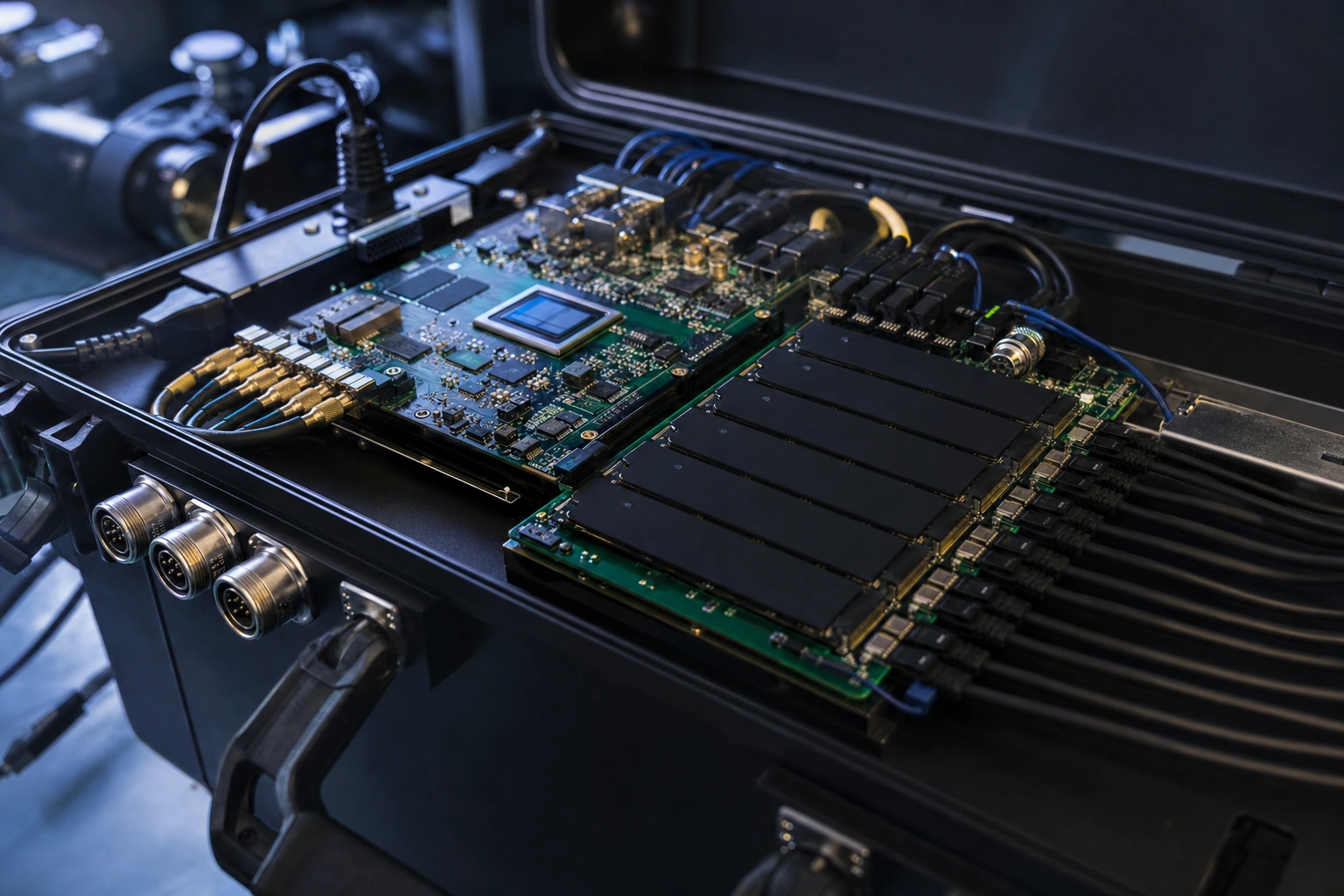
Industry update — On 11 August 2026, Microchip launched a Rev 2.0 PolarFire FPGA Ethernet Sensor Bridge — 60% smaller, USB-C powered, with 10 GbE and dual-camera support — aimed at edge data aggregation, the same capture-and-stream problem an on-FPGA NVMe recorder solves when the data rate outruns any CPU (Microchip, 11 August 2026).
A data recorder has one unforgiving job: capture a continuous stream — radar returns, video, sensor arrays, a flight-test bus — and write every byte to storage without ever falling behind. An NVMe Host Recorder IP core does exactly that for high-speed data acquisition: it turns an FPGA into a hardware NVMe host that streams capture straight to an SSD, with no processor and no operating system in the path. This guide explains how that architecture guarantees throughput, how to size it so it never drops a sample, and where it earns its place in avionics, defense and instrumentation.
The short answer
An NVMe Host Recorder IP core makes an FPGA a high-speed data acquisition recorder: it takes a continuous capture stream from your fabric and writes it to an NVMe SSD over PCIe, entirely in hardware, with deterministic timing and no CPU. The rule that decides success is simple — the SSD’s sustained write rate, fed by enough NVMe command queues, must comfortably exceed your peak capture rate, with headroom. Get that right and the recorder never drops a sample.
Why data acquisition belongs on an FPGA
Because an FPGA removes the operating-system scheduler from the capture path. Capture and storage both run as fixed-cadence hardware, so throughput is guaranteed rather than best-effort — the difference between a lossless recorder and one that drops samples under load.
Recorders fail in the gaps. A software-based DAQ system running on a processor depends on a scheduler deciding when the storage task runs; under load, that introduces jitter, and jitter on a continuous stream means lost data. An FPGA recorder removes the scheduler entirely. The capture path and the storage path are both hardware, running at a fixed, repeatable cadence. There is no operating system to stall and no driver to context-switch — the data simply flows from capture to SSD. That determinism is why data acquisition for flight test, radar and instrumentation is built on FPGAs rather than PCs whenever the capture must be guaranteed rather than best-effort.
How the recorder core works
The recorder core is the storage stage of a data acquisition chain. A capture source feeds a stream into the core; the core packs it into blocks, drives the NVMe command queues, and writes continuously to the SSD over PCIe — all in fabric, so throughput is bounded only by the link and the drive, not by software.
Think of the acquisition chain in three stages: a front end (an ADC, a video pipeline, or a data bus) digitises the signal; the FPGA fabric time-stamps and formats the capture; and the recorder core — a soft NVMe host IP core — commits it to the SSD. Because a recorder core is delivered as reusable RTL rather than fixed silicon, it is a soft IP core: you drop it into the FPGA family your system already uses. The whole chain lives in hardware, so throughput is bounded only by the PCIe link, the SSD and how well the command queues are fed — never by an operating system.
Sustained rate vs burst rate
Burst is the peak speed an SSD holds for a few seconds; sustained is the rate it holds forever. A recorder must be sized to the sustained rate, because the capture stream never pauses to let the drive catch up.
The single most common recorder mistake is sizing to an SSD’s burst number. SSD datasheets advertise peak write speeds that hold only briefly, before the drive’s internal housekeeping — garbage collection, wear levelling — pulls the rate down to its true sustained level. A data acquisition recorder must be designed to that sustained rate, because the capture stream never stops.
Equally, an NVMe link only reaches its potential when enough command queues are kept full in parallel. Under-feed the queues and even a fast PCIe generation delivers disappointing throughput. The NVM Express specification describes this multi-queue model, and industry storage-performance methodology (the SNIA solid-state performance work) exists precisely because sustained behaviour differs so sharply from the datasheet peak. A recorder core’s job is to exploit the multi-queue model so the sustained write rate is actually achieved.
Not sure whether your SSD and FPGA can sustain your capture rate? That question is exactly what a short technical review answers.
Sizing the recorder so it never drops
- Start from peak capture rate. Use the highest continuous rate your source produces, not the average.
- Match to SSD sustained write. Choose a drive whose sustained — not burst — write rate clears your peak with margin.
- Add headroom. A practical guideline is to provision sustained write capacity comfortably above peak capture, to absorb drive-to-drive variation.
- Buffer for the dips. On-FPGA buffering smooths the SSD’s brief slow-downs so the capture stream never stalls.
- Pick the PCIe generation accordingly. If the required sustained rate exceeds a Gen4 x4 link, a Gen5-capable host and FPGA family becomes necessary.
Making the media PC-readable
Layer an exFAT file-system core on top of the recorder and the FPGA writes files an operating system can open — still with no processor in the path. For removable-media field recorders, that is often the deciding feature.
Many recorders need the SSD to be removable and readable on a laptop in the field. Raw NVMe writes are not directly mountable, so an on-fabric exFAT layer lets the FPGA write files a PC can open. exFAT is the practical choice here because it is Microsoft’s documented format for high-capacity removable flash media, so any modern laptop mounts the drive with no special software. For portable data acquisition, that capability turns a raw capture into an evidence file an analyst can open immediately.
Where NVMe recorders are used
The NVMe recorder pattern shows up wherever high-rate data acquisition must be captured reliably. The common thread: the capture cannot be paused, and a dropped sample is a failed test.
| Domain | What is captured | Why an NVMe recorder |
|---|---|---|
| Avionics & flight test | Avionics data buses and sensor streams during test campaigns | Guaranteed, time-stamped capture across a whole flight; no PC to crash mid-test |
| Defense | Radar returns and wideband signal recording | High sustained rate in a rugged, certifiable box with deterministic timing |
| Instrumentation | High-channel-count measurement and high-frame-rate imaging | Fabric-rate capture that scales with channel count, not CPU load |
| Video | Multi-stream capture where dropped frames are unacceptable | Continuous writes to SSD with on-FPGA buffering to absorb drive dips |
When a different approach fits better
The NVMe recorder is built for guaranteed high-rate data acquisition. Other approaches fit when:
- Your rate is modest. If the capture comfortably fits within a SATA link, a SATA recorder is smaller and simpler to certify — the SATA host and device IP selection guide covers where that line sits.
- Data must stream off-board. If the destination is a server, an Ethernet or NVMe-over-Fabrics path beats a local SSD.
- You record rarely and briefly. For short, infrequent bursts, on-chip or external memory may suffice without a drive at all.
Frequently asked questions
What is an NVMe Host Recorder IP core?
An FPGA IP core that combines an NVMe host controller with recorder streaming logic, so the FPGA captures a continuous data acquisition stream and writes it to an NVMe SSD over PCIe in hardware, with no processor and deterministic timing.
How is this different from a PC-based DAQ system?
A PC’s scheduler introduces jitter that can drop samples on a continuous stream. An FPGA recorder runs the whole capture-to-storage path in hardware at a fixed cadence, so throughput is guaranteed rather than best-effort.
How do I stop a recorder from dropping data?
Size to the SSD’s sustained write rate, not its burst figure; keep enough NVMe command queues full to reach that rate; add headroom above peak capture; and buffer on the FPGA to absorb the drive’s brief slow-downs.
What is the difference between sustained and burst write rate?
Burst is the peak speed an SSD holds briefly before internal housekeeping reduces it; sustained is the rate it can hold indefinitely. A recorder must be designed to the sustained rate because the capture stream never pauses.
Can the recorder’s SSD be read on a PC afterwards?
Yes, by layering an exFAT file-system core on the recorder, so the FPGA writes OS-readable files with no processor in the path — useful for removable-media field recorders.
Where are NVMe FPGA recorders used?
Avionics and flight test, defense radar and signal recording, high-channel-count instrumentation, and multi-stream video capture — anywhere high-rate data acquisition must be captured without loss.
Designing a recorder that cannot drop a sample? Tell us your sustained capture rate and target FPGA, and we will point you to the right core or scope the build.
- NVM Express — NVMe specifications and the multi-queue command model
- PCI-SIG — PCI Express specifications for the recorder link
- JEDEC — SSD and NAND flash standards relevant to sustained-write behavior
- SNIA Solid State Storage Initiative — sustained vs burst performance methodology
- Microsoft — exFAT file system specification (removable-media format)