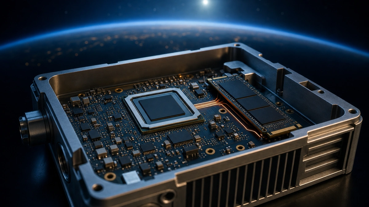
Industry update — Microchip expanded its PolarFire FPGA IP ecosystem with new SDI Rx/Tx video IP cores and a quad CoaXPress bridge kit, extending the same low-power, FPGA-native IP-core approach that host-side storage cores such as NVMe rely on this platform (Microchip, January 2026).
For a whole class of embedded systems — a satellite payload logging telemetry, an avionics unit recording a data bus, a remote sensor that has to run for years inside a tight power envelope — adding NVMe storage is not a contest for maximum throughput. It is about writing to an SSD reliably, in a small power and thermal budget, on a device that can survive where a conventional processor cannot. Microchip’s PolarFire SoC was built for that corner of the design space: a flash-based FPGA fabric, a hardened RISC-V processor subsystem, low static power, and a radiation-tolerant sibling for space. This guide looks at what makes PolarFire SoC a credible low-power host for NVMe, where its PCIe generation sets the ceiling, and how an NVMe Host IP core connects the two.
By Logic Design Solutions · FPGA storage & avionics IP engineering · Published 16 July 2026
- The short answer
- Why PolarFire SoC suits low-power NVMe
- What "low power" actually means here
- The radiation and space-adjacent angle
- The real constraint: PCIe generation
- How an NVMe Host IP core fits on PolarFire SoC
- Where the pairing earns its place
- When PolarFire is not the right NVMe host
- Frequently asked questions
The short answer
PolarFire SoC pairs a flash-based, low-static-power FPGA fabric with a hardened 64-bit RISC-V processor subsystem, which makes it a natural home for power- and radiation-sensitive systems that need local NVMe storage. Its embedded PCIe controller is a Gen2 block, so PolarFire is the right host for moderate-rate NVMe — telemetry, logging, edge capture — rather than the highest-bandwidth Gen4/Gen5 recorders. An NVMe Host IP core lets the fabric drive the SSD directly, keeping the storage path lean, deterministic and free of a heavyweight software stack.
Why PolarFire SoC suits low-power NVMe
Most FPGAs that host NVMe are SRAM-based: their configuration lives in volatile memory that must be reloaded from an external PROM every time the board powers up. PolarFire SoC is different. Microchip’s PolarFire family uses a non-volatile flash-based fabric, so the configuration is held on-chip and the device is effectively instant-on, with no external configuration memory to power, load or protect. For a storage subsystem that has to come up quickly and predictably after a power cycle — and there are many such systems in avionics and space — that is a meaningful architectural advantage before a single byte is written.
The second half of the story is the processor. PolarFire SoC integrates a hardened RISC-V Microprocessor Subsystem (MSS) built around 64-bit application cores plus a monitor core, coherent with the FPGA fabric. That means the same device can run the application — a Linux or RTOS control plane, the mission logic, the housekeeping — while the fabric handles the deterministic NVMe data path. You avoid bolting a separate microcontroller and its power draw onto the board just to supervise storage. Consolidating the processor, the fabric and the NVMe host onto one flash-based, low-power device is exactly the kind of integration that shrinks a board’s parts count and its energy budget.
What "low power" actually means here
It is worth being precise, because "low power" is a marketing phrase until you say what drives it. Microchip positions PolarFire and PolarFire SoC as low-power mid-range FPGAs, and the underlying reasons are structural rather than magical:
- Flash configuration draws less static power. A non-volatile fabric does not have to hold its configuration in leaky SRAM cells or reload it at every boot, which trims standby and static consumption compared with equivalent SRAM-based parts.
- No external configuration device. Removing the config PROM and its support circuitry removes a component that would otherwise consume power and board area.
- Low-power transceivers. PolarFire transceivers are designed to operate across a wide range of line rates, so a PCIe link to an SSD can run at the speed the application actually needs rather than always burning full-rate power.
- One device instead of two. Folding the control processor into the SoC removes a whole companion chip from the power budget.
What this article deliberately does not do is quote a wattage. Actual power depends on the device, the fabric utilisation, the transceiver rate, the SSD and the workload — and any single number would be misleading. Treat the low-power claim as directional: PolarFire SoC lets you build an NVMe host that lives in a tight energy budget, and the right way to confirm a figure for your design is to estimate it against your chosen device and workload. The exact power numbers for a specific part belong in Microchip’s device documentation, not in a blog post.
The radiation and space-adjacent angle
The same flash fabric that saves static power has a second consequence that matters far more in avionics and space: it is immune to configuration upsets. In an SRAM-based FPGA, a high-energy particle can flip a bit in the volatile configuration memory and silently corrupt the design — a single-event upset (SEU) in the config layer. PolarFire’s configuration lives in flash, which does not suffer that failure mode, so the device holds its programmed logic even in a radiation environment. Microchip productises this directly with the Radiation-Tolerant PolarFire SoC, a space-grade variant of the same architecture.
For an NVMe host, that changes the conversation. A telemetry recorder or a payload data store in a satellite, a high-altitude platform or a defense system can be built on an architecture whose configuration is inherently robust, rather than one that needs configuration scrubbing and triple-modular redundancy just to stay programmed. The storage logic still has to be designed for reliability — and the SSD and the data itself have their own radiation considerations — but the FPGA hosting it is starting from a stronger position. This is what we mean by "space-adjacent": PolarFire SoC is a natural fit not only for certified space missions but for the broad band of high-reliability, high-altitude and defense systems that share the same concerns without the full space-qualification programme.
Weighing PolarFire SoC against a larger SRAM FPGA for a power- or radiation-constrained storage design? That trade-off is exactly what a short technical review clarifies.
The real constraint: PCIe generation
Every honest PolarFire NVMe discussion has to arrive here. NVMe rides on PCIe, and the PCIe generation your host can drive sets the bandwidth ceiling. On PolarFire SoC, the embedded, hardened PCIe controller is a Gen2 block. Per Microchip’s PolarFire PCI Express User Guide, the PCIe subsystem supports configurations up to a x4 endpoint or root-port link. It does not provide the hardened Gen4 or Gen5 PCIe controllers found on larger, higher-end FPGA families.
| PCIe generation | Raw rate per lane | Approx. x4 raw bandwidth | Where it fits |
|---|---|---|---|
| Gen2 — PolarFire SoC | 5 GT/s | ~2 GB/s | Low-power, radiation-robust capture and logging |
| Gen4 | 16 GT/s | ~8 GB/s | Higher-end SoC/FPGA families with hardened Gen4 controllers |
| Gen5 | 32 GT/s | ~16 GB/s | Top-end recorders — see NVMe Host IP on Altera Agilex 7 R-Tile |
Moving up the ladder is a PHY-level change, not just a link-speed setting — we break that down in Gen4 vs Gen5 NVMe Host IP on FPGA. PolarFire SoC sits deliberately at the Gen2 rung, trading peak bandwidth for low power and configuration robustness.
What does a Gen2 link buy you? Using the PCI-SIG per-generation figures, PCIe Gen2 runs at 5 GT/s per lane, so a Gen2 x4 link offers on the order of 2 GB/s of theoretical raw bandwidth before protocol overhead. That is comfortably enough for a large set of real storage workloads — continuous telemetry, event logging, moderate-rate sensor capture, configuration and mission data — but it is well short of what a Gen4 or Gen5 host delivers for the most demanding recorders. The design implication is simple and it is the crux of choosing PolarFire for NVMe:
- If your sustained write rate fits within a Gen2 x4 budget, PolarFire SoC lets you host NVMe in a low-power, radiation-robust package that few other devices can match.
- If your workload needs the raw throughput of Gen4/Gen5, the PCIe ceiling — not the NVMe logic — is the deciding factor, and a higher-end FPGA family is the honest answer.
Sizing this correctly is the same discipline as any recorder design: work from the SSD’s sustained write rate, not its burst datasheet figure, keep the NVMe command queues fed, and leave headroom. The difference on PolarFire is that the Gen2 link is a fixed part of the envelope you are designing within.
How an NVMe Host IP core fits on PolarFire SoC
An FPGA cannot talk to an NVMe SSD by itself — NVMe is a specific command protocol layered on PCIe, defined by the NVM Express specification. Bridging the gap is the job of an NVMe Host IP core: a block that presents a simple read/write interface to your design on one side and drives the NVMe host controller, command queues and PCIe link to the SSD on the other. LDS’s NVMe Host IP — from an IP house that has shipped FPGA storage and avionics cores since 1994 — is designed to do exactly this — act as a hardware NVMe host so the FPGA can initialise an SSD and stream data to and from it directly.
On PolarFire SoC there are two natural ways to arrange it, and the choice follows the workload:
- Fabric-hosted, no CPU in the data path. The NVMe host logic sits in the flash fabric and drives the SSD over the PCIe link with deterministic timing. The RISC-V MSS supervises and configures but stays out of the byte-by-byte path, which is the pattern that gives a recorder its guaranteed, jitter-free behaviour.
- MSS-coordinated. Where the application is doing more than streaming — managing files, indexing, responding to commands — the RISC-V subsystem coordinates the storage while the fabric handles the heavy lifting, exploiting the coherency between the two.
If the media must later be read on a laptop in the field, an exFAT file-system layer on top of the host core lets the FPGA write OS-readable files rather than raw blocks — useful for removable recorders in test and field environments. When the goal is a continuous capture appliance rather than a general file store, the same core underpins a dedicated NVMe host recorder data path. The integration mechanics differ across SoC families; our Zynq UltraScale+ integration guide walks through the equivalent steps on a Xilinx SoC. The general point is that the NVMe Host IP is what turns PolarFire SoC’s low-power, radiation-robust platform into an actual storage subsystem, within the Gen2 bandwidth envelope described above.
Where the pairing earns its place
PolarFire SoC plus an NVMe Host IP core is at its strongest wherever storage has to be reliable and power- or environment-constrained rather than maximally fast:
| Domain | Typical role | Why PolarFire SoC fits |
|---|---|---|
| Space & satellite payloads | Telemetry and payload-data logging to local SSD | Flash config immune to configuration upsets; RT PolarFire SoC space-grade variant; tight power budget; instant-on after power cycles |
| Avionics & flight test | Recording data buses and sensor streams during test | Deterministic hardware data path; high-reliability, radiation-robust architecture; integrated RISC-V for mission logic |
| Defense & rugged edge | Signal and event recorders in harsh, size-limited enclosures | Low power and small parts count; single-device consolidation of processor, fabric and NVMe host |
| Remote / autonomous edge | Long-duration sensor capture on a fixed energy budget | Low static power from flash fabric; Gen2 x4 bandwidth is ample for moderate-rate capture |
The common thread is that none of these workloads are chasing the absolute peak of PCIe bandwidth. They are chasing reliable capture inside constraints — power, radiation, size, boot time — which is precisely the axis on which PolarFire SoC is strong.
When PolarFire is not the right NVMe host
Choosing the platform honestly means naming where a different device wins:
- You need Gen4/Gen5 throughput. If the sustained write rate exceeds what a Gen2 x4 link provides, the PCIe ceiling decides it — a higher-end FPGA with a hardened Gen4/Gen5 controller is the right host — our NVMe Host IP on Altera Agilex 7 R-Tile covers exactly that Gen5 case.
- Power and radiation are not concerns. If the design lives in a benign, mains-powered environment, PolarFire’s flash-fabric advantages matter less, and the decision comes down to bandwidth and cost.
- The workload is compute-heavy, not storage-heavy. If most of the effort is in the application rather than the storage path, the FPGA/SoC choice should be driven by that logic, with NVMe a secondary consideration.
PolarFire SoC is a deliberate choice for the low-power, high-reliability end of the spectrum — not a universal NVMe host. Used where its strengths line up with the mission, it is hard to beat.
Need an NVMe host or storage IP core for your FPGA? Our engineers ship production-proven cores for AMD and Altera devices.
Frequently asked questions
Can Microchip PolarFire SoC host NVMe storage?
Yes. PolarFire SoC has an embedded PCIe controller and a RISC-V processor subsystem, and with an NVMe Host IP core in the fabric it can initialise and stream data to an NVMe SSD directly, within a Gen2 PCIe bandwidth envelope.
What PCIe generation does PolarFire SoC support?
Its hardened, embedded PCIe controller is a Gen2 block, supporting configurations up to a x4 link per Microchip’s PCI Express User Guide. It does not include hardened Gen4 or Gen5 PCIe controllers.
Is PolarFire SoC bandwidth enough for NVMe?
For moderate-rate workloads — telemetry, logging, edge and sensor capture — a Gen2 x4 link (on the order of 2 GB/s theoretical, per PCI-SIG figures) is ample. For the highest-bandwidth recorders that need Gen4/Gen5, a higher-end FPGA family is the right host.
Why is PolarFire SoC considered low power?
Chiefly because its fabric is flash-based rather than SRAM-based, which lowers static power and removes the external configuration device, and because folding the RISC-V processor into the SoC removes a companion chip. Actual power depends on the device and workload and should be estimated against Microchip’s device documentation.
Why does PolarFire SoC suit space and avionics?
Its flash configuration is immune to configuration single-event upsets, so the device holds its programmed logic in radiation environments. Microchip also offers a radiation-tolerant RT PolarFire SoC variant for space-grade missions.
Do I need a CPU in the NVMe data path on PolarFire SoC?
No. The NVMe Host IP can run entirely in the fabric with deterministic timing, while the RISC-V subsystem supervises and configures without sitting in the byte-by-byte path — the pattern that gives recorders their jitter-free behaviour.
Building a low-power or radiation-robust storage design on PolarFire SoC? Tell us your sustained write rate, target device and environment, and we will confirm the fit or scope the NVMe host.
- Microchip — Radiation-Tolerant PolarFire SoC FPGAs (flash fabric, space-grade variant)
- Microchip — PolarFire FPGA and PolarFire SoC PCI Express User Guide (Gen2 controller, up to x4)
- NVM Express — NVMe specifications and the host command model
- PCI-SIG — PCI Express specifications and per-generation lane rates