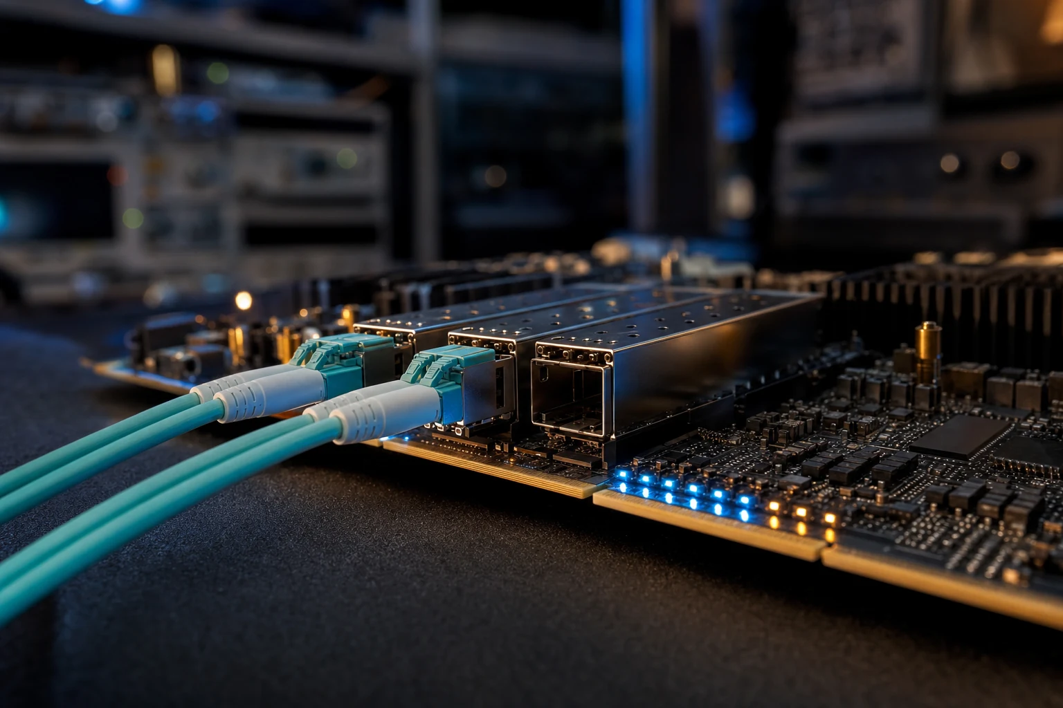
Industry news — On 8 September 2026 CAST introduced TCPIP-100G, a hardware TCP/IP stack IP core running at up to 100 Gbps with support for 32,768 simultaneous TCP sessions and a selectable cut-through mode for lowest latency — and it ships with sample designs that pair it with third-party Ethernet MAC and memory-controller IP on the major AMD and Altera FPGA families, a reminder that the MAC is the layer every other block in an FPGA network stack sits on top of (Design&Reuse, 8 September 2026).
In short: A 10G Ethernet MAC IP core builds and checks IEEE 802.3 frames in FPGA fabric between your application logic and a PCS/PMA block — and the value of a good one is in its per-frame status reporting, its flow control and its portability, not in the line rate every 10G MAC shares.
Read that announcement carefully and one detail matters more than the headline number: a 100 Gbps hardware TCP/IP stack does not put a single bit on a fibre by itself. It hands frames down to a media access control block, the MAC hands symbols to a PCS/PMA, and only then does anything reach an SFP+ cage. Every FPGA networking design has that same floor underneath it — a TCP offload engine, a UDP streamer, a raw-frame telemetry capture, an ATA-over-Ethernet storage target — and the floor is the MAC. This article is about that floor at 10 Gbps: what the block does, why you would license one rather than take the vendor’s hard MAC or write your own, and what a real, shipping 10G Ethernet MAC IP core exposes on its transmit and receive interfaces.
- The short answer
- What a 10G Ethernet MAC IP does inside an FPGA
- Hard MAC, home-grown RTL, or a licensed 10G Ethernet MAC IP
- The transmit path: FIFOs, pause frames and configuration
- The receive path: error taxonomy and filtering
- Where it sits: PCS/PMA, one clock domain, and not a PHY
- The eight validated targets and their evaluation boards
- Why AoE frame recognition is in the statistics at all
- Low latency: what a 10G Ethernet MAC IP can and cannot give you
- Where this stops applying
- Frequently asked questions
The short answer
A 10G Ethernet MAC IP core is the soft-logic block that turns payload
bytes inside your FPGA into valid IEEE 802.3 frames on the wire, and frames on the wire back
into payload plus a verdict on what arrived. Logic Design Solutions licenses one —
ETH_MAC_10G_SFP — described on its own product page as an IP that
“incorporates one Ethernet MAC at 10Gbits on a FPGA and is compliant with IEEE802.3ae
specification”. It is a soft core, it is not a PHY, and it is “designed to be connected
to a PCS/PMA IP with only one clock domain”. Eight variants are published: a generic core plus
seven builds validated on named evaluation boards across AMD and Microchip silicon. Resource,
frequency and latency figures depend on your device and configuration; ask for them for your exact
target.
What a 10G Ethernet MAC IP does inside an FPGA
The media access control sublayer is the part of Ethernet that deals in frames rather
than in signals. Everything below it — encoding, serialisation, the optical launch
— is the physical layer. Everything above it belongs to whatever protocol stack you put there,
or to nothing at all if your application streams raw frames.
On transmit the MAC builds the frame around your payload: destination and source addresses,
optional VLAN tags, the length or type field, padding up to the 64 bytes minimum frame size
IEEE 802.3 mandates, and a 4 bytes frame check sequence. It then presents that frame with
the required spacing — the inter-frame gap, 96 bits of idle, or 12 bytes
at any Ethernet rate. On receive it does the mirror image: recovers frame boundaries, checks the CRC,
checks the declared length against the payload, decides whether the destination address is one this
station should accept, and strips what the application does not want to see.
The happy path is mechanical. The engineering is in everything else: a failed CRC, a receive FIFO
that backs up mid-frame, a pause frame from the link partner, a fault raised by the physical layer, an
oversized frame because jumbo frames are enabled at one end of the link and not the other. A MAC that
reports precisely which of eleven things went wrong, per frame, is a product; one that only
handles good frames is a weekend project.
Hard MAC, home-grown RTL, or a licensed 10G Ethernet MAC IP
Three routes are open to a team that needs 10 Gbps Ethernet out of an FPGA, and all three are
used in production. They differ in what they cost you later, not in whether they work.
The vendor’s own MAC. AMD, Altera and Microchip all offer Ethernet MAC blocks,
some hardened on specific families, some delivered as vendor soft IP through the tool flow. Where one
exists on the device you have already chosen and covers your feature set, it is hard to beat. What
you give up is portability and visibility: the design does not move to another vendor’s silicon
without rework at that boundary, and you generally cannot read or extend the RTL — which matters
when an acceptance test wants a statistic the block does not count.
Writing it yourself. An experienced team can write a 10G MAC; framing, CRC-32 and
address filtering are well-documented problems. The cost is the long tail of IEEE 802.3
behaviours — pause-frame semantics, control-frame handling, fault signalling from the
reconciliation sublayer, correct truncation on overflow — plus proving all of it against an
unforgiving link partner. That is schedule risk on a project whose real differentiation is elsewhere.
Licensing a soft core. Licensing puts a pre-verified, portable block in your
fabric with the RTL available to you. LDS delivers its cores in VHDL source form, which makes the same
MAC deployable on a Kintex 7 and on a PolarFire without a redesign, and lets you add a counter or
change a filter policy when your system demands it. Our note on
soft IP versus hard IP covers that
trade-off in general.
The transmit path: FIFOs, pause frames and configuration
The transmit side is organised around a pair of FIFO interfaces plus three control interfaces, and
the split is the design’s central idea: payload and per-frame policy arrive on separate paths, so your
application logic never interleaves control information into the data stream. A transmit data
FIFO interface carries the payload. Alongside it a
transmit status FIFO interface exists, in the product page’s own words,
“to define if the CRC has to be append or to transmit a Error Control character”.
Appending the CRC is the normal case; not appending it means your logic supplies its own
frame check sequence, which is what you need when forwarding a frame you received intact or emitting
a deliberately corrupt CRC from a test system. The error control character option is the
other half: the 10 Gbps encoding carries a defined error character, and injecting it deliberately
tests how the far end reacts to corruption.
Two interfaces deal with flow control. A transmit pause interface lets your logic
request a pause frame on demand; a transmit FIFO RX pause interface asks the MAC to
send one automatically when the receive FIFO becomes nearly full. The second matters for any receiver
that must not drop frames: the backpressure decision is taken in hardware, at the point of congestion,
with no round trip through software. On a capture or storage target at line rate, that is the
difference between a paused link and a truncated frame.
A transmit configuration interface sets the device Ethernet address, the padding
behaviour and the inter-frame gap — configurable rather than constant, because the standard sets
only a minimum and deterministic industrial links and test equipment sometimes need to run wider. The
transmit statistics interface then reports, per frame, what actually went out:
- Frame byte sent, and frame done
- Unicast, multicast and broadcast frames
- Control frames, pause frames, AoE frames
- VLAN frames and stacked VLAN frames
- FIFO underrun
- Frames carrying an error control character
- Frames flushed because of a bad start of frame
The last three are the diagnostics you will want at three in the morning: a FIFO underrun says your
logic could not keep up with the wire, a flushed frame says the handshake into the MAC went wrong
before the frame started, and neither is visible from the far end.
The receive path: error taxonomy and filtering
The receive side mirrors that structure — a receive data FIFO for payload
and a receive status FIFO for the verdict — but the verdict is where the value
is. A MAC that says only “good” or “bad” forces you to guess. This one
distinguishes, per frame:
- Frame error — the catch-all, asserted when any error occurred
- Frame length error or payload length error — declared length and delivered
payload disagree - CRC error — the frame check sequence did not verify
- Frame truncated due to receive FIFO overflow — your side could not drain
fast enough, and the MAC says so rather than corrupting the stream silently - Frame corrupted due to PHY error, control code error — the fault came from
below the MAC - Wrong code received from the reconciliation sublayer and local or remote
fault error — link-level rather than frame-level conditions - VLAN, stacked VLAN, AoE and good
frame flags, plus the recorded payload length
Those categories are not interchangeable, and that is the point. A CRC error means the bits were
disturbed in flight: look at the optics, the cable, the connector. A truncation on FIFO overflow means
the wire was fine and your own design is the bottleneck. A local or remote fault, signalled by the
reconciliation sublayer, means the link is down or the far end cannot receive — and
surfacing it saves you from diagnosing a dead fibre as a software bug.
What the receiver accepts
The receive configuration interface decides what gets through: the device Ethernet
address, a configurable maximum frame length with jumbo frames available, promiscuous mode, remove
frame padding, forward CRC, forward pause frames, ignore pause frame quanta, payload length check
disable, ignore control frame, and a mode the product page states plainly as “Accept only AoE
and Pause Frame”. A hash table interface sits alongside for multicast
filtering.
Read that list as decisions about where work happens. Remove frame padding and
forward CRC decide whether your application sees the raw frame or a cleaned payload;
promiscuous mode and the hash table decide whether address filtering costs you fabric
downstream or nothing at all. The receive statistics interface then counts the same
taxonomy in aggregate, down to frame-too-long and frame-too-short errors, wrong codes from the
reconciliation sublayer, and local or remote faults. On a link you cannot physically reach, those
counters are your only instrument.
Where it sits: PCS/PMA, one clock domain, and not a PHY
The MAC is not a PHY, and confusing the two is the most common integration mistake on a first 10G
design. LDS states the boundary explicitly: the core is “designed to be connected to a PCS/PMA
IP with only one clock domain”. ETH_MAC_10G_SFP expects a physical coding sublayer
and physical medium attachment block beneath it — typically the vendor’s own PCS/PMA core
driving the device’s serial transceivers — and expects to run in that block’s clock domain
rather than to bridge two.
That decision removes a class of clock-domain-crossing logic along with its latency and its
verification burden. It also means the MAC does not absorb a rate mismatch for you: the FIFOs at the
application boundary are where your system clock meets the network clock — a deliberate place
for it rather than an accident buried inside the MAC. Simpler and more predictable, but it requires
you to plan the clocking of the surrounding design.
Above the MAC, everything is your choice; the CAST stack in the news hook is one example. Below
it, the PCS/PMA and the SFP+ module handle encoding, serialisation and the optics. For the
layer-by-layer walk through framing and that boundary, see our companion article on
10G Ethernet framing,
PCS/PMA and FPGA integration.
The eight validated targets and their evaluation boards
Eight ETH_MAC_10G_SFP variants are published: one generic core and seven builds each validated on
a named evaluation board. Naming the board matters more than naming the family, because a validated
build implies a specific transceiver type, SFP+ cage wiring and constraint set — the things
that consume the first fortnight of a bring-up.
| Target family | Evaluation board named by LDS | Silicon vendor |
|---|---|---|
| Generic (device-independent core) | None — the base IP, not tied to a board | — |
| Kintex 7 | KC705 evaluation board | AMD |
| Kintex UltraScale | KCU105 evaluation board | AMD |
| Virtex 7 | VC707 evaluation board | AMD |
| Zynq 7 | ZC706 evaluation board | AMD |
| Zynq UltraScale+ | ZCU102 evaluation board | AMD |
| Zynq UltraScale+ | ZCU106 evaluation board | AMD |
| PolarFire | PolarFire Evaluation Kit | Microchip |
Two things follow. Zynq UltraScale+ appears twice, on two different boards — not redundancy,
because ZCU102 and ZCU106 differ in their peripheral complements, and a build proven on the board you
own beats one proven on its sibling. And PolarFire alongside the AMD families is the portability claim
made concrete: Microchip’s flash-based fabric has a different transceiver architecture and tool flow,
so a core that has been through bring-up on both sides has absorbed differences a datasheet hides.
What the published material does not give is per-device resource utilisation or maximum frequency.
LDS has published no LUT, flip-flop or block-RAM count for this core on any of these targets, and this
article will not estimate them. Ask for them for your exact target.
Why AoE frame recognition is in the statistics at all
AoE is ATA over Ethernet, and finding it counted as a first-class frame type in a
general-purpose MAC is unusual enough to explain. AoE carries storage commands directly inside
Ethernet frames, with its own registered EtherType and no IP or TCP layer underneath: on a controlled,
switched local network, removing the routing and transport layers removes their latency, their
buffering and their software. Linux supports it natively, which makes an AoE target usable without a
proprietary initiator on the host.
It appears in this MAC because LDS sells the layer above it. The company’s NOE SAN
IP, announced in February 2026, implements ATA over Ethernet v1.0 for NVMe SSDs over networks
from 10 GbE up to 400 GbE, with JBOD support, jumbo frames and the Write, Read and Identify
command set, on Agilex 7-i, Zynq UltraScale+ and Kintex UltraScale. When your storage-networking
IP speaks AoE, the MAC beneath it has to recognise AoE frames in hardware — which is what the
“Accept only AoE and Pause Frame” receive mode is for. A target configured that way drops
every frame that is neither storage traffic nor flow control before it reaches the fabric above: a
performance decision and a security posture at once.
The AoE counters on both statistics interfaces let a storage node account for its own traffic
without an external probe. From the storage side, our pieces on
NVMe SAN IP for storage networks and
NVMe over fabrics on FPGA cover the layer above this
MAC. The lineage is consistent: the LDS SATA recorder line carried AoE and jumbo-frame support
alongside its 1 Gbit and 10 Gbit MAC options, with a published jumbo limit of
9216 bytes, years before NOE SAN existed.
Low latency: what a 10G Ethernet MAC IP can and cannot give you
Latency in an FPGA network stack is decided mostly above the MAC. The MAC’s own contribution is a
small, fixed pipeline: framing, CRC generation or checking, and the FIFO boundary at the application
interface. It is bounded and deterministic, which is the property that matters in hardware. It is not
where the milliseconds live.
The decision that dominates end-to-end latency is cut-through versus store-and-forward,
and it is taken above the MAC, not inside it. Store-and-forward buffers a complete frame before acting
on it, so a full-size frame costs at least its own serialisation time before anything downstream
begins; cut-through starts forwarding as soon as the header is readable, at the cost of propagating
frames whose CRC later proves bad. That is exactly what the CAST announcement at the top of this
article exposes as a selectable mode — in the stack, above a MAC. The MAC’s job is to expose
frame boundaries and status cleanly enough that a cut-through design above it is possible at all.
Three practical levers do sit at the MAC boundary: jumbo frames, which cut per-frame overhead but
raise worst-case store-and-forward delay; hardware pause generation from the
receive-FIFO-nearly-full trigger, which spares a congested receiver a software round trip; and the
single-clock-domain PCS/PMA attachment, which removes crossing logic from the datapath. None of those
is a latency figure, and this article will not invent one: LDS has published no latency number
for this core, and the only measured throughput figure the company has ever published is
roughly 500 MB/s on a single 6 Gbit SATA link, in a 2019 news item about a different product
line. Ask for cycle-accurate latency against your exact target, and get it in writing.
Tell us your target device, your PCS/PMA choice and what sits above the MAC — raw frames, a protocol stack or an AoE storage target — and we will tell you what the core needs on that device and what it will report back to you.
Where this stops applying
This article describes one core, at one rate, in one position in the stack. The boundaries:
- This is a 10 Gbps MAC, and only that. If you need 25, 40 or 100 GbE,
this core is not the answer — ask what is, because the requirement changes the transceiver, the
PCS and often the device. - It is not a PHY and not a switch. You still need a PCS/PMA IP, transceivers and
an SFP+ front end. Nothing here performs switching, routing or any layer-3 function. - No performance figures are published. Resource utilisation, maximum frequency and
latency are not in the public material, and nothing here estimates them. - Validation on a board is not certification. The seven named boards mean bring-up
has been done on that hardware. If you work to DO-254 or a comparable regime, the design assurance
level and the documentation package are a separate conversation. - Low latency is a system property. Cut-through behaviour, buffering strategy and
protocol offload are decided above the MAC. A fast MAC inside a store-and-forward architecture does
not produce a low-latency system.
In summary
A 10G Ethernet MAC IP core is the layer everything else in an FPGA network design
stands on, and the useful way to evaluate one is not the headline rate every 10G MAC shares but what
it tells you when things go wrong. On that measure ETH_MAC_10G_SFP is specific: separate data and
status FIFOs in both directions, per-frame control over CRC append and error-character injection,
hardware-triggered pause generation from a nearly-full receive FIFO, and a receive error taxonomy
that distinguishes a bad cable from a slow application from a dead link.
It is IEEE 802.3ae compliant, it attaches to a PCS/PMA IP in a single clock domain, and it is
published on eight targets across AMD and Microchip silicon. The AoE recognition on both statistics
interfaces is not decoration; it is the hook for the ATA-over-Ethernet storage line above it. What the
public material does not contain is resource, frequency or latency data — ask for that against
your device and configuration rather than accept an estimate from anyone.
Frequently asked questions
What is the difference between a 10G Ethernet MAC IP and a PHY?
The MAC works in frames; the PHY works in signals. A 10G Ethernet MAC IP core builds frames on transmit — addressing, padding, the frame check sequence, the inter-frame gap — and validates them on receive. The physical layer below it handles encoding, serialisation and the optical or electrical launch. LDS states the boundary explicitly: ETH_MAC_10G_SFP is designed to connect to a PCS/PMA IP with a single clock domain. You still need that PCS/PMA block, the device transceivers and an SFP+ front end to have a working link.
Why licence a 10G Ethernet MAC IP instead of using the FPGA vendor’s hard MAC?
Portability and visibility. A vendor MAC is supported and characterised on that vendor’s silicon, and if it covers your feature set it is hard to beat on cost. But a design built on it does not move to another vendor’s device without rework at that boundary, and you generally cannot read or extend the RTL. A soft core delivered in VHDL source runs on Kintex 7 and on PolarFire from the same design, and can be extended when a customer requirement asks for a counter or a filter policy the original block never had.
Which FPGA families is the LDS 10G Ethernet MAC validated on?
Eight variants are published: a generic device-independent core, plus builds validated on Kintex 7 with the KC705 board, Kintex UltraScale with the KCU105, Virtex 7 with the VC707, Zynq 7 with the ZC706, Zynq UltraScale+ on both the ZCU102 and the ZCU106, and Microchip PolarFire with the PolarFire Evaluation Kit. The first six are AMD devices; the last is Microchip. A build validated on the specific board you own removes most of the first fortnight of bring-up work.
How does the core handle flow control and congestion?
Two ways, and the second is the interesting one. A transmit pause interface lets your logic request a pause frame on demand. A separate transmit FIFO RX pause interface asks the MAC to emit a pause frame automatically when the receive FIFO becomes nearly full. That decision happens in hardware, at the point of congestion, with no software round trip. On the receive side you can independently forward pause frames upward, ignore the pause quanta, or ignore control frames entirely.
Why does an Ethernet MAC count AoE frames?
Because LDS sells the layer above it. ATA over Ethernet carries storage commands directly in Ethernet frames with no IP or TCP underneath, and the LDS NOE SAN IP announced in February 2026 implements AoE v1.0 for NVMe SSDs on Agilex 7-i, Zynq UltraScale+ and Kintex UltraScale. A storage target needs its MAC to recognise AoE traffic in hardware, which is what the receive mode that accepts only AoE and pause frames is for, and what the AoE counters on both statistics interfaces measure.
What latency and resource utilisation should I expect?
LDS has published neither, and this article does not estimate them. The MAC’s own contribution to latency is a small fixed pipeline — framing, CRC and the FIFO boundary — bounded and deterministic, but end-to-end latency is dominated by decisions above the MAC, principally cut-through versus store-and-forward buffering. Resource utilisation depends on device family, speed grade and configuration. Ask for both against your exact target, and treat any figure you have not received in writing as unknown.
- IEEE 802.3 Ethernet Working Group — IEEE 802.3 Ethernet Standard: the standards body that defines Ethernet framing, the frame check sequence, the inter-frame gap and the reconciliation sublayer this MAC implements.
- IEEE 802.3ae Task Force — IEEE P802.3ae 10 Gb/s Ethernet Task Force: the task force whose specification ETH_MAC_10G_SFP is stated to comply with.
- Logic Design Solutions — ETH_MAC_10G_SFP product page: the transmit and receive feature lists, error taxonomy, configuration options and statistics quoted throughout this article.
- Logic Design Solutions — ETH_MAC_10G_SFP PolarFire variant: the Microchip PolarFire build, validated with the PolarFire Evaluation Kit.
- Logic Design Solutions — NOE SAN IP available, 13 February 2026: the ATA-over-Ethernet SAN IP for NVMe SSDs that explains why AoE recognition sits in the MAC’s statistics.
- Linux kernel documentation — ATA over Ethernet (AoE) driver: reference for native AoE support in Linux, the host side of an FPGA AoE target.
- Microchip Technology — PolarFire FPGA Evaluation Kit: the Microchip evaluation platform named in the PolarFire variant of the core.
- Design&Reuse — CAST introduces 100 Gbps TCP/IP hardware stack IP core, 8 September 2026: the September 2026 announcement of a hardware TCP/IP stack that pairs with third-party Ethernet MAC IP, cited in the opening.