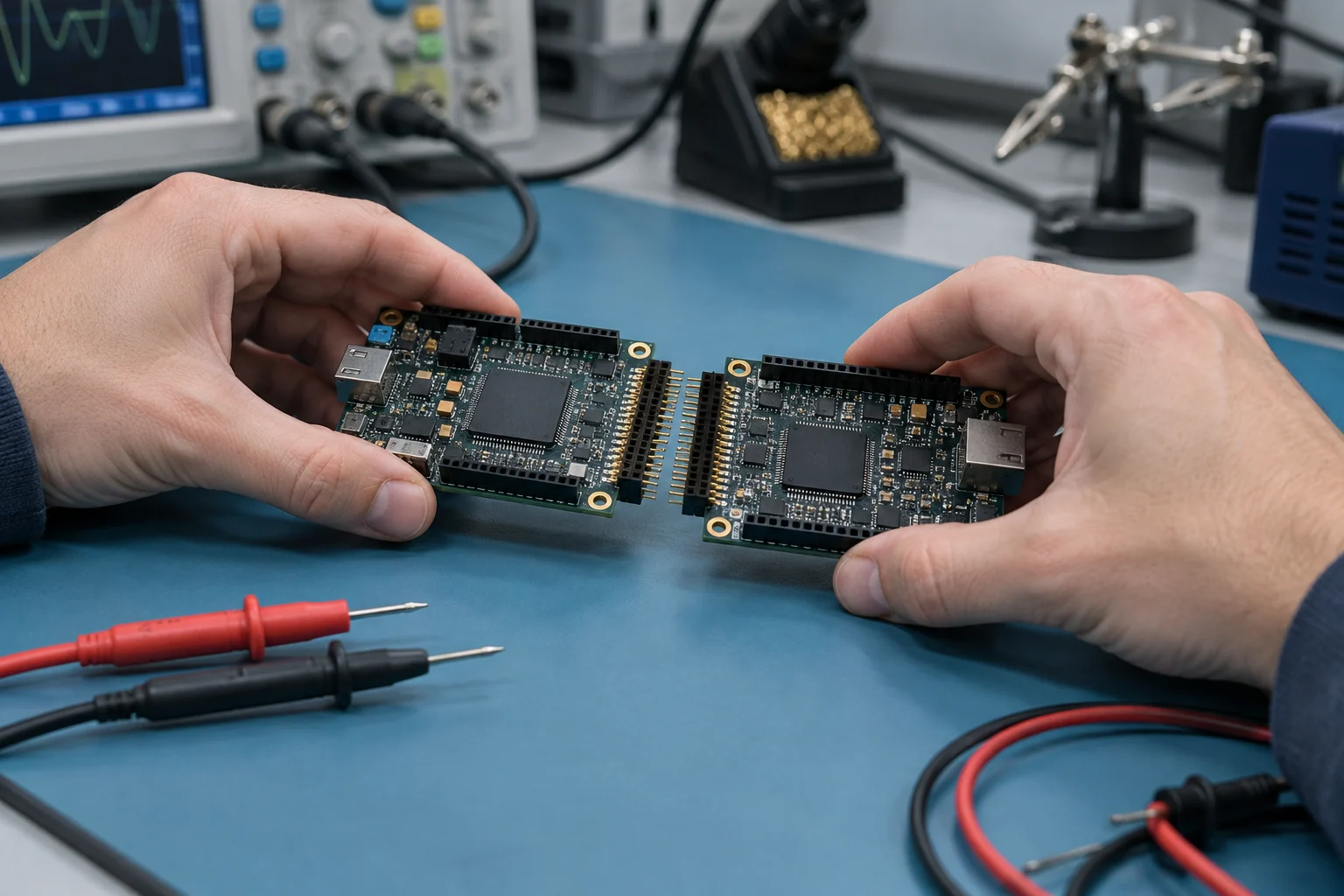
FPGA IP core selection starts with the exact core and intended FPGA family, then checks interfaces, handoff artifacts, and evidence against the project’s acceptance criteria. If any link is missing, keep compatibility or fit unresolved rather than treating a family name or broad portability claim as proof.
The short answer
We recommend selecting an FPGA IP core only when its documentation covers the exact intended FPGA family and the project’s acceptance criteria specify the required interfaces, HDL or netlist handoff, integration artifacts, and deployment-relevant verification evidence.
Start with the target, not the portability claim: prioritize documentation for the exact FPGA family and intended use. A broad portability statement, or evidence for a related device, does not establish compatibility with the specific target and use case.
Treat each boundary separately. Assess the core, controller, and wrapper individually, then state whether the requirement covers one bounded responsibility or a grouped subsystem, with ownership assigned for any remaining integration, timing, verification, or development work.
This rule defines a selection approach, not a compatibility finding for a particular core. Its limit is the evidence and scope stated in the documentation and acceptance criteria.
How should compatibility be checked across Altera, Microchip and Xilinx FPGA families?
Check each intended core-family pair independently, and mark compatibility established only when the core’s documentation covers the target and the project’s agreed acceptance check is met.
ESA’s description of its own IP cores says they are technology-independent soft cores that can be synthesized and targeted to any ASIC or FPGA. That gives us a useful review principle, not proof that a different core supports a particular Altera, Microchip, or Xilinx family.
Apply the same review independently to every intended family. Make the matrix the working record: give each core-family pair its own row, with fields for the exact core, target family, documentation statement, target-specific constraints or deliverables, and agreed acceptance evidence. The row should capture what the documentation says, not fill gaps with assumptions. When details are missing, leave them open rather than treating support as confirmed.
There are two useful ways to start. A portability-led review starts with a technology-independent claim, then asks whether the core’s documentation covers the intended target. A family-led review starts with the target and looks for explicit support in the core’s documentation. Both approaches lead to the same practical question: what evidence supports this specific pairing? Our recommendation is to use documentation to screen each pair, then use a target-specific acceptance check, such as a build or another project-appropriate artifact, before marking compatibility established.
Do not treat a family name as proof of compatibility. Support for one family does not establish support for another, so keep each status unresolved when its evidence is incomplete. Keep each target separate.
Our custom FPGA development article lists eight phases: specification, architecture and device selection, RTL design, integration, timing closure, verification, bring-up and delivery. Use device selection to record the intended family, then carry that target into the project’s acceptance criteria. This connects the portability review to the development sequence, but the sequence itself does not establish support for a particular device.
Does the core include the interfaces the system needs?
Count an interface as included only when its IP description names a matching deliverable; a core name alone does not establish that its controller or integration wrapper is included.
The ESA description of HurriCANe 5.2.4 lists a CAN core, a CAN controller, and an AMBA APB wrapper, and describes the wrapper as integrating the CAN core into a system-on-chip. Names are only the starting point.
Begin with the system’s interface requirements, not with a candidate’s name. For each requirement, record its name, its role, and the exact wording in the package description that supports a match. Keep that wording beside the requirement so the decision remains traceable to the stated deliverable.
- List each interface the system requires.
- Match each requirement to a specifically named deliverable.
- Keep the core, controller, and wrapper separate when the description lists them separately.
- Keep an interface unresolved if the description does not name it.
For a CAN-based system-on-chip, the ESA entry provides a concrete example: record the CAN core, CAN controller, and AMBA APB wrapper as separate items, rather than treating the core name as evidence for all three. The HurriCANe portfolio description identifies those deliverables and explains the wrapper’s role.
A name-only shortlist can identify candidates, but it does not answer whether the named deliverables match the same interface requirements. Use one requirement list for every candidate, then compare the descriptions against it. Match every required interface to an explicitly named deliverable, and leave unsupported matches visible in the selection record. Treat the result as a coverage check, not a complete decision about whether the core fits the wider design.
Our recommendation: use the requirement-to-deliverable comparison to decide whether a core fits. If the question extends beyond interface coverage, our article on the scope of FPGA design services states that a full FPGA design service spans five stages and can begin at any one of them.
Which HDL, netlist and integration artifacts fit the design flow?
Choose an IP core by matching its design-entry method and handoff artifacts to the receiving flow, then specify the HDL, netlist, and integration files the project must accept.
Microchip’s Libero design-entry documentation lists SmartDesign, VHDL, Verilog, and SystemVerilog as design-entry methods, and describes SmartDesign as a block-based tool. Use that documentation as a flow-specific reference, not as a universal handoff specification.
Our recommendation: make every requested handoff item an acceptance criterion. Keep the brief readable by separating two questions: how is the design entered, and what must the receiving flow accept? A broad compatibility label does not answer both. Keep the categories distinct.
- Design entry: Name the selected method and HDL language separately. If the required language is Verilog, for example, state Verilog explicitly rather than treating a tool or method name as a substitute.
- HDL and netlist: State whether the handoff must include HDL, a netlist, or both, and specify the required format for each.
- Integration artifacts: Name each required file or document and its format. Include only items the receiving design needs, and mark each as mandatory or optional.
The linked documentation can inform the design-entry part of the brief, but the project requirements determine which handoff items belong in the package. Use the design phases as prompts, then specify the artifacts the selected core must provide for the receiving flow.
When the brief names the entry method and language separately, then states whether HDL, a netlist, or both are required, the technical review has a defined set of deliverables to assess against the design flow.
Is one core enough, or does the design need a composable subsystem?
We recommend one core when the requirement names one bounded responsibility; choose a composable subsystem when acceptance depends on evaluating several functions together.
Single IP core or composable subsystem?
Start with the acceptance question, not the size of the design. Write down what must be judged, then decide whether that responsibility stands on its own or whether the requirement groups several functions for joint evaluation. That answer sets the selection boundary.
| Selection criterion | One core | Composable subsystem |
|---|---|---|
| Requirement | The requirement names one responsibility. | The requirement groups several responsibilities for joint evaluation. |
| Acceptance question | Can the selection be judged against that responsibility alone? | Does the decision depend on assessing the grouped responsibilities together? |
| Selection boundary | Keep the scope around the stated responsibility. | Name the included functions and what remains outside the combined scope. |
For example, if a requirement names one responsibility while adjacent functions sit in the broader design, keep those functions outside the selection unless the requirement groups them for joint evaluation. If it does group them, state which functions belong in the subsystem and which remain outside it. Keep the selection boundary aligned with the acceptance question, rather than expanding the scope simply because you could.
Keep the boundary narrow. If the combined requirement is unclear, define its scope before choosing a subsystem; otherwise, keep the decision at core level and compare against the narrower requirement.
Logic Design Solutions’ custom FPGA development article and its eight project phases list specification, architecture and device selection, RTL design, integration, timing closure, verification, bring-up and delivery. Use those labels to locate where the selection decision starts and ends, not as a reason to include every phase in an IP purchase.
This comparison sets scope; it does not determine whether a particular core or subsystem meets technical requirements beyond the acceptance question. Our recommendation is to keep that distinction explicit: choose the selection boundary from the requirement, then assess the chosen scope against it.

What verification evidence should match the deployment environment?
Verification evidence should match the deployment context it actually covers: identify the core and configuration, distinguish test activity from a result or prediction, and keep mission-specific claims within the evidence’s stated scope.
NASA’s FPGA single-event-effects guidance names core evaluation, fault injection, and mission-specific, system-level SEU response prediction. Use that scope to frame the record: state whether the IP core is embedded or user-inserted, which core and configuration it covers, which tests were performed, and which deployment context they address.
A test label is not enough.
For single-event effects, NASA lists heavy-ion energy and linear energy transfer (LET) selection, proton versus heavy-ion testing, and mean fluence to failure analysis among its FPGA evaluation areas. Keep the evidence categories distinct: a test activity says what was done; an analysis says what was evaluated; a reported result or prediction says what the document actually states. Do not turn a record of an activity into a result, or present a listed evaluation area as a finding for a particular design.
We recommend matching each test claim to the intended deployment context. Put a general statement that testing occurred beside the specific evidence for the core, configuration, and mission under review. For an embedded core, keep that status visible alongside the relevant configuration; for a user-inserted core, preserve that distinction. NASA’s guidance names evaluation of both embedded and user-inserted IP cores.
Give particular attention to the mission-specific, system-level SEU response. Keep the mission context and the connection between the evaluated core and predicted response visible in the review. NASA names response prediction as an evaluation area, but its guidance alone does not establish a result for a particular design.
Keep verification and bring-up evidence distinct. A custom FPGA development outline lists 8 phases, including verification and bring-up. Separate verification evidence from bring-up evidence and map each item to the phase it supports, so the review shows what the supplied evidence covers and what remains open for the intended deployment.
When should selection extend from an IP license to integration engineering or custom development?
We recommend extending an IP license only when the remaining design work has no owner: use integration engineering for unresolved integration or timing closure, and custom development when specification or architecture remains open.
Keep the scope tied to ownership. Start with the earliest unresolved deliverable, then name who owns it. If your team owns the remaining design and integration, keep the scope license-only. If a selected core still needs integration or timing closure, include integration engineering for that work. When the open work reaches specification or architecture, custom development is the more coherent scope.
Ownership sets the boundary.
That approach aligns with Logic Design Solutions’ description of its FPGA design service: the FPGA design-services article describes five stages and says a partner can enter at any one. Use that outline to locate the work you need covered, rather than treating every stage as part of every engagement. It is a service outline, not a project-specific assignment of responsibility.
For work that still reaches specification or architecture, the custom-development phase outline lists eight phases, from specification and architecture through verification, bring-up, and delivery. Use those phases to identify where the unresolved deliverable sits; the list does not mean every phase belongs in your scope. Our recommendation is to include only the work needed to cover the responsibility that would otherwise remain unassigned.
| Scope | Boundary to use |
|---|---|
| IP license | Your team owns the remaining design and integration work. |
| Integration engineering | The core is selected, but integration or timing closure still needs an owner; both appear in the custom-development phase outline. |
| Custom development | The open work reaches specification or architecture, phases included in the custom-development outline. |
Before extending the scope, state the unfinished deliverable and its owner. If responsibility is already assigned, a broader scope is not justified by the phase list alone; if it is not, extend only far enough to cover that gap.
What remains unproven without current device-specific compatibility evidence?
Without current evidence tied to the exact FPGA device and intended use, compatibility remains unproven. We recommend keeping the core conditional, not treating it as a confirmed fit or an incompatible one.
Match the evidence to the exact target and intended use. A record about a related device, configuration, or use case can provide context, but it does not establish fit for the design at hand. Keep that distinction visible in the decision record, rather than letting a similar example stand in for evidence about the target.
For example, if the available material concerns a related device rather than the exact target, record what it does cover and what it leaves unanswered. Then state the requirement in the design’s own terms and identify what evidence would address that gap. This keeps the question specific: the issue is not whether the material is useful, but whether it answers the requirement that matters to the decision.
Keep the gap visible.
Our decision rule is to separate unanswered questions by their importance to the choice. If a must-have requirement remains unanswered, leave approval open. If the project accepts the point as an assumption, document the assumption, its owner, and what decision would change if it proves false. That makes the boundary of the decision explicit without claiming more than the available evidence supports.
Before committing, make the record answer three questions: which exact target and intended use does the evidence cover, which project requirement remains unaddressed, and what would need to change in the selection if that answer stays unavailable? Keep the evidence and its scope attached to the decision, so a later review can follow what the original choice relied on instead of having to infer it.
If a decision-critical question remains unanswered, do not turn uncertainty into a compatibility claim or a verdict of incompatibility. Leave the core conditional until the missing point is resolved, or state the assumption explicitly if the project chooses to proceed without it.
In summary
Create a selection record for each intended family: name the exact core and target, map every required interface to a named deliverable, and specify the required HDL, netlist, and integration artifacts. Set the acceptance check before marking compatibility confirmed.
Then match each verification claim to the core, configuration, and deployment context it covers, and assign an owner to every remaining task. Leave must-have gaps pending; document accepted assumptions and what would change the decision if one proves false.
How we wrote this article
The sources we consulted are listed at the end of the article, consulted on 2 October 2026. Where we cite none, it is our opinion, and we write it as such.
This article gives buying criteria and our point of view. It does not replace a professional’s advice on a specific situation.
It is published by Logic Design Solutions, which therefore has an interest in the subject.
Sources
- ESA – About ESA IP Cores, esa.int
- ESA – ESA HDL IP Cores Portfolio Overview, esa.int
- NASA Electronic Parts and Packaging (NEPP) Field Programmable Gate Array (FPGA) Single Event Effects (SEE) Test Guidelines, ntrs.nasa.gov
- Libero® SoC Features – Developer Help, developerhelp.microchip.com
- FPGA Design Services: What an IP-Focused Design House Delivers – Logic Design Solutions | Logic Design Solutions, logic-design-solutions.com
- Custom FPGA Development: From Spec to Validated Bitstream – Logic Design Solutions | Logic Design Solutions, logic-design-solutions.com